


Welcome to Free Ebook Engineering http://freebooks-me.blogspot.com!
Showing posts with label Electronic. Show all posts
Showing posts with label Electronic. Show all posts
Introduction to Electric Circuits - 886 pages
Thursday, September 15, 2016
Views:
BY Anonymous
0 COMMENTS
0 COMMENTS
Richard C. Dorf, James A. Svoboda
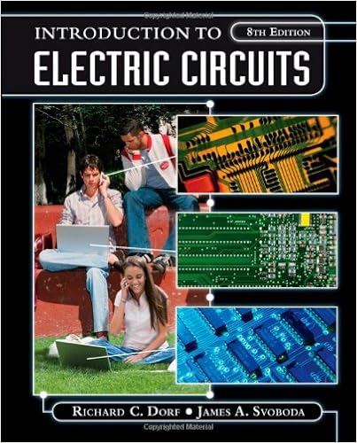
Give Your Students Real-World Problem-Solving Skills!As in earlier editions, the central theme of Introduction to Electric Circuits, 8th Edition, is the concept that electric circuits are a part of the basic fabric of modern technology. Given this theme, this book endeavors to show how the analysis and design of electric circuits are inseparably intertwined with the ability of the engineer to design complex electronic, communication, computer, and control systems as well as consumer products. This book is designed for a one-to-three-term course in electric circuits or linear circuit analysis, and is structured for maximum flexibility.
New to this Edition: Enhanced WileyPLUS course with 300 algorithmic problems, bringing the total set of assignable algorithmic problems to over 600. These algorithmically generated problems allow students to practice repeatedly the same problem type with new values.Significantly increased use of computational software PSpice and MATLAB.Revisions made throughout the text to improve clarity.The text contains 120 new problems, brining the total number to more than 1,350. This edition uses a progression of problem types that range in difficulty.
You have options with Wiley Flex!

The central theme of Introduction to Electric Circuits is the concept that electric circuits are a part of the basic fabric of modern technology. Given this theme, this book endeavors to show how the analysis and design of electric circuits are inseparably intertwined with the ability of the engineer to design complex electronic, communication, computer and control systems as well as consumer products.This book is designed for a one-to three-term course in electric circuits or linear circuit analysis, and is structured for maximum flexibility.
Noted for its historical vignettes and informal writing style, this edition features new design problems written with ABET accreditation standards, which provide practice in applying material to interesting design situations. New summary design examples demonstrate step-by-step techniques to solve design problems.
Table of contents :
Cover......Page 1
Title Page......Page 2
Copyright......Page 3
About the Authors......Page 5
Preface......Page 6
Contents......Page 14
1.2 Electric Circuits and Current......Page 21
1.3 Systems of Units......Page 25
1.5 Power and Energy......Page 27
1.6 Circuit Analysis and Design......Page 31
1.7 How Can We Check . . . ?......Page 33
1.8 Design Example—Jet Valve Controller......Page 34
Problems......Page 35
Design Problems......Page 39
2.2 Engineering and Linear Models......Page 40
2.3 Active and Passive Circuit Elements......Page 43
2.4 Resistors......Page 45
2.5 Independent Sources......Page 48
2.6 Voltmeters and Ammeters......Page 50
2.7 Dependent Sources......Page 53
2.8 Transducers......Page 57
2.9 Switches......Page 59
2.10 How Can We Check . . . ?......Page 60
2.11 Design Example—Temperature Sensor......Page 62
Problems......Page 64
Design Problems......Page 72
3.1 Introduction......Page 73
3.2 Kirchhoff's Laws......Page 74
3.3 Series Resistors and Voltage Division......Page 83
3.4 Parallel Resistors and Current Division......Page 88
3.5 Series Voltage Sources and Parallel Current Sources......Page 94
3.6 Circuit Analysis......Page 97
3.7 Analyzing Resistive Circuits Using MATLAB......Page 102
3.8 How Can We Check . . . ?......Page 106
3.9 Design Example—Adjustable Voltage Source......Page 108
3.10 Summary......Page 111
Problems......Page 112
Design Problems......Page 132
4.1 Introduction......Page 134
4.2 Node Voltage Analysis of Circuits with Current Sources......Page 135
4.3 Node Voltage Analysis of Circuits with Current and Voltage Sources......Page 141
4.4 Node Voltage Analysis with Dependent Sources......Page 146
4.5 Mesh Current Analysis with Independent Voltage Sources......Page 148
4.6 Mesh Current Analysis with Current and Voltage Sources......Page 153
4.7 Mesh Current Analysis with Dependent Sources......Page 157
4.8 The Node Voltage Method and Mesh Current Method Compared......Page 159
4.9 Circuit Analysis Using MATLAB......Page 162
4.10 Using PSpice to Determine Node Voltages and Mesh Currents......Page 164
4.11 How Can We Check . . . ?......Page 166
4.12 Design Example—Potentiometer Angle Display......Page 169
4.13 Summary......Page 172
Problems......Page 173
Design Problems......Page 187
5.2 Source Transformations......Page 189
5.3 Superposition......Page 196
5.4 Thévenin’s Theorem......Page 200
5.5 Norton’s Equivalent Circuit......Page 207
5.6 Maximum Power Transfer......Page 211
5.7 Using MATLAB to Determine the Thévenin Equivalent Circuit......Page 214
5.8 Using PSpice to Determine the Thévenin Equivalent Circuit......Page 217
5.9 How Can We Check . . . ?......Page 220
5.10 Design Example—Strain Gauge Bridge......Page 221
5.11 Summary......Page 223
Problems......Page 224
PSpice Problems......Page 236
Design Problems......Page 237
6.2 The Operational Amplifier......Page 239
6.3 The Ideal Operational Amplifier......Page 241
6.4 Nodal Analysis of Circuits Containing Ideal Operational Amplifiers......Page 243
6.5 Design Using Operational Amplifiers......Page 248
6.6 Operational Amplifier Circuits and Linear Algebraic Equations......Page 253
6.7 Characteristics of Practical Operational Amplifiers......Page 258
6.8 Analysis of Op Amp Circuits Using MATLAB......Page 265
6.9 Using PSpice to Analyze Op Amp Circuits......Page 267
6.10 How Can We Check . . . ?......Page 268
6.11 Design Example—Transducer Interface Circuit......Page 270
6.12 Summary......Page 272
Problems......Page 273
PSpice Problems......Page 285
Design Problems......Page 287
7.1 Introduction......Page 288
7.2 Capacitors......Page 289
7.3 Energy Storage in a Capacitor......Page 295
7.4 Series and Parallel Capacitors......Page 298
7.5 Inductors......Page 300
7.6 Energy Storage in an Inductor......Page 305
7.7 Series and Parallel Inductors......Page 307
7.8 Initial Conditions of Switched Circuits......Page 308
7.9 Operational Amplifier Circuits and Linear Differential Equations......Page 312
7.10 Using MATLAB to Plot Capacitor or Inductor Voltage and Current......Page 318
7.11 How Can We Check . . . ?......Page 320
7.12 Design Example—Integrator and Switch......Page 321
7.13 Summary......Page 324
Problems......Page 325
Design Problems......Page 341
8.2 First-Order Circuits......Page 342
8.3 The Response of a First-Order Circuit to a Constant Input......Page 345
8.4 Sequential Switching......Page 358
8.5 Stability of First-Order Circuits......Page 360
8.6 The Unit Step Source......Page 362
8.7 The Response of a First-Order Circuit to a Nonconstant Source......Page 366
8.8 Differential Operators......Page 371
8.9 Using PSpice to Analyze First-Order Circuits......Page 372
8.10 How Can We Check . . . ?......Page 375
8.11 Design Example—A Computer and Printer......Page 379
8.12 Summary......Page 382
Problems......Page 383
PSpice Problems......Page 394
Design Problems......Page 395
9.1 Introduction......Page 398
9.2 Differential Equation for Circuits with Two Energy Storage Elements......Page 399
9.3 Solution of the Second-Order Differential Equation—The Natural Response......Page 403
9.4 Natural Response of the Unforced Parallel RLC Circuit......Page 406
9.5 Natural Response of the Critically Damped Unforced Parallel RLC Circuit......Page 409
9.6 Natural Response of an Underdamped Unforced Parallel RLC Circuit......Page 410
9.7 Forced Response of an RLC Circuit......Page 412
9.8 Complete Response of an RLC Circuit......Page 416
9.9 State Variable Approach to Circuit Analysis......Page 419
9.10 Roots in the Complex Plane......Page 423
9.11 How Can We Check . . . ?......Page 424
9.12 Design Example—Auto Airbag Igniter......Page 427
9.13 Summary......Page 429
Problems......Page 431
PSpice Problems......Page 442
Design Problems......Page 443
10.1 Introduction......Page 445
10.2 Sinusoidal Sources......Page 446
10.3 Phasors and Sinusoids......Page 450
10.4 Impedances......Page 455
10.5 Series and Parallel Impedances......Page 460
10.6 Mesh and Node Equations......Page 467
10.7 Thévenin and Norton Equivalent Circuits......Page 474
10.8 Superposition......Page 479
10.9 Phasor Diagrams......Page 481
10.10 Op Amps in AC Circuits......Page 483
10.11 The Complete Response......Page 485
10.12 Using MATLAB to Analyze AC Circuits......Page 492
10.13 Using PSpice to Analyze AC Circuits......Page 494
10.14 How Can We Check . . . ?......Page 496
10.15 Design Example—An Op Amp Circuit......Page 499
10.16 Summary......Page 501
Problems......Page 502
PSpice Problems......Page 522
Design Problems......Page 523
11.2 Electric Power......Page 524
11.3 Instantaneous Power and Average Power......Page 525
11.4 Effective Value of a Periodic Waveform......Page 529
11.5 Complex Power......Page 532
11.6 Power Factor......Page 539
11.7 The Power Superposition Principle......Page 547
11.8 The Maximum Power Transfer Theorem......Page 550
11.9 Coupled Inductors......Page 551
11.10 The Ideal Transformer......Page 559
11.11 How Can We Check . . . ?......Page 566
11.12 Design Example—Maximum Power Transfer......Page 567
11.13 Summary......Page 569
Problems......Page 571
PSpice Problems......Page 586
Design Problems......Page 587
12.1 Introduction......Page 588
12.2 Three-Phase Voltages......Page 589
12.3 The Y-to-Y Circuit......Page 592
12.4 The Delta-Connected Source and Load......Page 601
12.5 The Y-to-Delta Circuit......Page 603
12.6 Balanced Three-Phase Circuits......Page 606
12.7 Instantaneous and Average Power in a Balanced Three-Phase Load......Page 608
12.8 Two-Wattmeter Power Measurement......Page 611
12.9 How Can We Check . . . ?......Page 614
12.10 Design Example—Power Factor Correction......Page 617
12.11 Summary......Page 618
Problems......Page 619
PSpice Problems......Page 622
Design Problems......Page 623
13.2 Gain, Phase Shift, and the Network Function......Page 624
13.3 Bode Plots......Page 636
13.4 Resonant Circuits......Page 653
13.5 Frequency Response of Op Amp Circuits......Page 660
13.6 Plotting Bode Plots Using MATLAB......Page 662
13.7 Using PSpice to Plot a Frequency Response......Page 664
13.8 How Can We Check . . . ?......Page 666
13.9 Design Example—Radio Tuner......Page 670
13.10 Summary......Page 672
Problems......Page 673
PSpice Problems......Page 686
Design Problems......Page 688
14.1 Introduction......Page 690
14.2 Laplace Transform......Page 691
14.3 Pulse Inputs......Page 697
14.4 Inverse Laplace Transform......Page 700
14.5 Initial and Final Value Theorems......Page 707
14.6 Solution of Differential Equations Describing a Circuit......Page 709
14.7 Circuit Analysis Using Impedance and Initial Conditions......Page 710
14.8 Transfer Function and Impedance......Page 720
14.9 Convolution......Page 726
14.10 Stability......Page 730
14.11 Partial Fraction Expansion Using MATLAB......Page 733
14.12 How Can We Check . . . ?......Page 738
14.13 Design Example—Space Shuttle Cargo Door......Page 740
14.14 Summary......Page 743
Problems......Page 744
PSpice Problems......Page 758
Design Problems......Page 759
15.2 The Fourier Series......Page 761
15.3 Symmetry of the Function f (t)......Page 770
15.4 Fourier Series of Selected Waveforms......Page 775
15.5 Exponential Form of the Fourier Series......Page 777
15.6 The Fourier Spectrum......Page 785
15.7 Circuits and Fourier Series......Page 789
15.8 Using PSpice to Determine the Fourier Series......Page 792
15.9 The Fourier Transform......Page 797
15.10 Fourier Transform Properties......Page 800
15.11 The Spectrum of Signals......Page 804
15.12 Convolution and Circuit Response......Page 805
15.13 The Fourier Transform and the Laplace Transform......Page 808
15.14 How Can We Check . . . ?......Page 810
15.15 Design Example—DC Power Supply......Page 812
15.16 Summary......Page 815
Problems......Page 816
Design Problems......Page 822
16.2 The Electric Filter......Page 824
16.3 Filters......Page 825
16.4 Second-Order Filters......Page 828
16.5 High-Order Filters......Page 836
16.6 Simulating Filter Circuits Using PSpice......Page 842
16.7 How Can We Check . . . ?......Page 846
16.8 Design Example—Anti-Aliasing Filter......Page 848
Problems......Page 851
PSpice Problems......Page 856
Design Problems......Page 859
17.1 Introduction......Page 860
17.2 T-to-Π Transformation and Two-Port Three-Terminal Networks......Page 861
17.3 Equations of Two-Port Networks......Page 863
17.4 Z and Y Parameters for a Circuit with Dependent Sources......Page 866
17.5 Hybrid and Transmission Parameters......Page 868
17.6 Relationships Between Two-Port Parameters......Page 870
17.7 Interconnection of Two-Port Networks......Page 872
17.8 How Can We Check . . . ?......Page 875
17.9 Design Example—Transistor Amplifier......Page 877
Problems......Page 879
Design Problems......Page 883
APPENDIX A Getting Started with PSpice......Page 885
APPENDIX B MATLAB, Matrices, and Complex Arithmetic......Page 893
APPENDIX C Mathematical Formulas......Page 905
APPENDIX D Standard Resistor Color Code......Page 909
References......Page 911
Index......Page 913
Download

ELECTRONICS FOR ELECTRICIANS & ENGINEERS
Friday, September 2, 2016
IN
Basic Electrical Engineering
,
Electrical and Electronics Engineering
,
Electrical Machines I
,
Electronic
,
Electronics
Views:
BY Anonymous
0 COMMENTS
0 COMMENTS
ELECTRONICS FOR ELECTRICIANS & ENGINEERS
Ian R. Sinclair
1987
ISBN-10: 0831110007
ISBN-13: 9780831110000
Pages: 270
Industrial Press, Inc.
other link
a Mirror DOWNLOAD
Mirror
Ian R. Sinclair
1987
ISBN-10: 0831110007
ISBN-13: 9780831110000
Pages: 270
Industrial Press, Inc.
Component data books are often little more than collections of specifications with little or nothing in the way of explanation or application and, in many cases, with so much information crammed into a small space that the user has difficulty in selecting what is needed. The cost of publishing paper data books, the rate that new products are being brought to market and the ease with which electronic copies of data sheets can be distributed by e-mail or downloaded from websites has begun to deter manufacturers from printing data books at all. This book, now in its sixth edition, has been extensively revised, with a large amount of new material added, to serve the needs of both the professional and the enthusiast. It combines data and explanations in a way that is not served by websites.
Although the book is not intended as a form of beginners’ guide to the whole of electronics, the beginner will find much of interest in the early chapters as a compact reminder of electronic principles and circuits. The constructor of electronic circuits and the service engineer should both find the data in this book of considerable assistance, and the professional design engineer will also find that the items brought together here include many that will be frequently useful and which would normally be available in collected form in much larger volumes.
The book has been designed to include within a reasonable space most of the information that is useful in day-to-day electronics together with brief explanations which are intended to serve as reminders rather than full descriptions. In addition, topics that go well beyond the scope of simple practical electronics have been included so that the reader has access to information on the advanced technology that permeates so much of modern electronics.

Content:
Front Matter, Page iii
Copyright, Page iv
Preface, Page v
Introduction: Mathematical Conventions, Pages 1-2
Chapter 1 - Passive Components, Pages 3-43
Chapter 2 - Active Discrete Components, Pages 44-71
Chapter 3 - Discrete Component Circuits, Pages 72-97
Chapter 4 - Linear I.C.s, Pages 98-118
Chapter 5 - Digital I.C.s, Pages 119-180
APPENDIX I - Standard metric wire table, Page 181
APPENDIX II - Bibliography, Pages 182-183
Index, Pages 184-186
Although the book is not intended as a form of beginners’ guide to the whole of electronics, the beginner will find much of interest in the early chapters as a compact reminder of electronic principles and circuits. The constructor of electronic circuits and the service engineer should both find the data in this book of considerable assistance, and the professional design engineer will also find that the items brought together here include many that will be frequently useful and which would normally be available in collected form in much larger volumes.
The book has been designed to include within a reasonable space most of the information that is useful in day-to-day electronics together with brief explanations which are intended to serve as reminders rather than full descriptions. In addition, topics that go well beyond the scope of simple practical electronics have been included so that the reader has access to information on the advanced technology that permeates so much of modern electronics.
Content:
Front Matter, Page iii
Copyright, Page iv
Preface, Page v
Introduction: Mathematical Conventions, Pages 1-2
Chapter 1 - Passive Components, Pages 3-43
Chapter 2 - Active Discrete Components, Pages 44-71
Chapter 3 - Discrete Component Circuits, Pages 72-97
Chapter 4 - Linear I.C.s, Pages 98-118
Chapter 5 - Digital I.C.s, Pages 119-180
APPENDIX I - Standard metric wire table, Page 181
APPENDIX II - Bibliography, Pages 182-183
Index, Pages 184-186
a Mirror DOWNLOAD
Mirror
Automobile Electrical and Electronic Systems - Tom Denton
Friday, March 18, 2016
IN
car
,
Electrical
,
Electronic
,
Electronics
,
engineering
,
Mechanical
,
Mechanical Engineering
,
Vehicle Dynamics
Views:
BY Anonymous
0 COMMENTS
0 COMMENTS

In the beginning, say 115 years ago, a book on vehicle electrics would have been very small. A book on vehicle electronics would have been even smaller!
As we continue our drive into the new millennium, the subject of vehicle electrics is becoming ever larger. Despite the book likewise growing larger, some aspects of this topic have inevitably had to be glossed over, or left out. However, the book still covers all of the key subjects and students, as well as general readers, will find plenty to read in the new edition.
This third edition has once again been updated and extended by the inclusion of more case studies and technology sections in each chapter. Multiple choice questions have also been added to most chapters.
Subject coverage soon gets into a good depth; however, the really technical bits are kept in a separate
section of each chapter so you can miss them out if you are new to the subject.
I have concentrated, where possible, on underlying electrical and electronic principles. This is because new systems are under development all the time.
Current and older systems are included to aid the reader with an understanding of basic principles.
To set the whole automobile electrical subject in context, the first chapter covers some of the significant
historical developments and dares yet again to speculate on the future.
download links
http://cutt.us/euhJJ
http://cutt.us/gwdJ2
This textbook will help you learn all the skills you need to pass Level 3 Vehicle Electrical and Electronic Systems courses or related modules from City and Guilds, IMI Awards and BTEC. It is also ideal for ASE, AUR and higher level qualifications.
As electrical and electronic systems become increasingly more complex and fundamental to the workings of modern vehicles, understanding these systems is essential for automotive technicians. For students new to the subject, this book will help to develop this knowledge, but will also assist experienced mechanics in keeping up with recent technological advances. This new edition includes information on developments in hybrid car technology, GPS, multiplexing, and electronic stability/vehicle dynamics control. In full colour and covering the latest course specifications, this is the guide that no student enrolled on an automotive maintenance and repair course should be without.
Designed to make learning easier, this book contains:
Photographs, flow charts, quick reference tables, overview descriptions and step-by-step instructions
Case studies to help you put the principles covered into real-life context
Useful margin features throughout, including definitions, key facts and ‘safety first’ considerations
Cover......Page 1
Automobile Electrical and Electronic Systems......Page 4Contents......Page 6
Preface......Page 10
Introduction to the third edition......Page 11
Acknowledgements......Page 12
1.1.1 Where did it all begin?......Page 14
1.1.2 A chronological history......Page 16
1.2.2 An eye on the future......Page 21
1.3.2 Project......Page 23
2.2.1 Introduction......Page 24
2.2.3 Effects of current flow......Page 25
2.2.7 Factors affecting the resistance of a conductor......Page 26
2.2.8 Resistors and circuit networks......Page 27
2.2.9 Magnetism and electromagnetism......Page 28
2.2.11 Mutual induction......Page 29
2.2.12 Definitions and laws......Page 30
2.3.2 Components......Page 31
2.3.3 Integrated circuits......Page 33
2.3.4 Amplifiers......Page 34
2.3.6 Schmitt trigger......Page 36
2.3.8 Filters......Page 37
2.3.11 Digital to analogue conversion......Page 38
2.4.1 Introduction to digital circuits......Page 39
2.4.3 Combinational logic......Page 40
2.4.5 Timers and counters......Page 41
2.4.6 Memory circuits......Page 42
2.5.1 Introduction......Page 43
2.5.5 Buses......Page 44
2.5.7 A typical microprocessor......Page 45
2 Task definition......Page 46
4 Coding......Page 47
2.6.3 Sources of error in measurement......Page 48
2.7.1 Thermistors......Page 49
2.7.2 Thermocouples......Page 50
2.7.4 Hall effect......Page 51
2.7.5 Strain gauges......Page 52
2.7.7 Variable resistance......Page 53
2.7.9 Linear variable differential transformer (LVDT)......Page 54
2.7.12 Vortex flow sensor......Page 55
2.7.16 Oxygen sensors......Page 56
2.7.18 Thick-film air temperature sensor......Page 57
2.7.20 Rain sensor......Page 58
2.7.24 Solenoid actuators......Page 59
2.7.25 Motorized actuators......Page 60
2.7.26 Stepper motors......Page 61
2.8 New developments......Page 63
2.9.1 Introduction......Page 65
2.9.2 Testing sensors......Page 66
2.10.1 Lambda sensor – case study......Page 67
2.11.2 Project......Page 68
2.11.3 Multiple choice questions......Page 69
3.1.2 Basic hand tools......Page 70
3.1.3 Accuracy of test equipment......Page 71
3.2.1 Basic test meters......Page 72
3.2.2 How to use a multimeter......Page 73
3.3.1 Oscilloscopes......Page 74
3.3.3 Engine analysers......Page 75
Waveforms......Page 76
3.3.4 Exhaust gas measurement......Page 77
3.4.1 Introduction......Page 79
3.4.3 Laser 2000 electronic systems tester......Page 80
3.5 On-board diagnostics......Page 81
3.6.3 Integrated diagnostic and measurement systems......Page 82
3.6.5 Multi Protocol Adapter (MPA)......Page 83
Diagnostic sequences......Page 84
3.7.2 The ‘theory’ of diagnostics......Page 85
3.7.3 Waveforms......Page 86
3.8.1 Bosch diagnostic system – case study......Page 90
Introduction......Page 91
Equipment Available......Page 92
3.9.3 Multiple choice questions......Page 93
4.1.2 Vehicle systems......Page 95
4.2.1 Cables......Page 96
4.2.2 Colour codes and terminal designations......Page 97
4.2.3 Harness design......Page 98
4.2.4 Printed circuits......Page 100
4.2.5 Fuses and circuit breakers......Page 101
4.2.6 Terminations......Page 102
4.2.7 Switches......Page 103
4.3.1 Limits of the conventional wiring system......Page 104
4.3.4 CAN signal format......Page 106
4.3.6 Fibre optics for multiplex databus......Page 108
4.3.8 Summary of CAN......Page 109
4.4.1 Symbols......Page 110
4.5.1 The smart electrical system of the future – Volvo S80......Page 111
4.6.2 Examples of EMC problems......Page 113
Introduction......Page 116
Visteon Bluetooth technology......Page 117
Microsoft Windows Automotive......Page 118
4.7.2 Beyond multiplexing......Page 119
4.7.3 Controller Area Networks (CAN) update......Page 120
4.8.3 Multiple choice questions......Page 121
5.1.3 Positioning the vehicle battery......Page 123
5.2.2 Battery rating......Page 124
5.3.2 Charging the lead-acid battery......Page 125
5.4.1 Servicing batteries......Page 126
5.4.3 Testing batteries......Page 127
5.5.1 Electrochemistry......Page 128
5.5.4 Electrochemical action of the lead-acid battery......Page 129
Efficiency......Page 131
5.6.1 Lead-acid battery developments......Page 132
5.6.3 The ZEBRA battery......Page 133
5.6.6 Fuel cell developments......Page 134
5.6.7 Sodium sulphur battery......Page 135
5.6.8 The Swing battery......Page 136
5.7.1 Bosch silver battery – case study......Page 137
5.7.2 Fuel cells – Dana......Page 138
Honda’s fuel cell stack......Page 139
5.8.3 Multiple choice questions......Page 140
6.1.2 Vehicle electrical loads......Page 141
6.2.2 Charging voltages......Page 142
6.3.1 Generation of electricity......Page 143
6.3.2 Rectification of AC to DC......Page 144
6.3.3 Regulation of output voltage......Page 146
6.3.4 Charging circuits......Page 148
6.4.2 Bosch compact alternator......Page 149
6.4.3 Japanese alternator......Page 150
6.4.4 LI-X series of alternators from Bosch......Page 151
6.6.1 Charging system – problems and solutions......Page 152
6.6.3 Alternator characteristics......Page 155
6.7.1 General developments......Page 156
Basic operating principles......Page 157
Closed loop regulation of output voltage......Page 158
Battery lifetime......Page 159
Summary......Page 160
6.8.3 Multiple choice questions......Page 161
7.1.1 Engine starting requirements......Page 162
7.1.3 Choosing a starter motor......Page 163
7.2.1 Starting system circuits......Page 164
7.2.2 Principle of operation......Page 165
7.2.3 DC motor characteristics......Page 166
7.3.1 Inertia starters......Page 168
7.3.2 Pre-engaged starters......Page 169
7.3.3 Permanent magnet starters......Page 170
7.3.4 Heavy vehicle starters......Page 172
7.3.7 Starter installation......Page 173
7.4.3 Ford integrated startergenerator (ISG)......Page 174
7.6.1 Speed, torque and power......Page 178
7.7.1 Belt-driven starter-generator......Page 180
7.8.1 Questions......Page 181
7.8.3 Multiple choice questions......Page 182
8.1.4 Advance angle (timing)......Page 183
Spark plug......Page 184
Vacuum advance......Page 185
8.1.8 Ignition coil cores......Page 186
8.2.2 Constant dwell systems......Page 187
8.2.4 Hall effect pulse generator......Page 188
8.2.6 Other pulse generators......Page 189
8.2.7 Dwell angle control (open loop)......Page 190
8.2.9 Capacitor discharge ignition......Page 192
Engine load – manifold absolute pressure sensor......Page 193
Detonation – knock sensor......Page 194
8.3.3 Electronic control unit......Page 195
Ignition output......Page 196
8.4.2 System components......Page 197
8.6.1 Functional requirements......Page 198
8.6.3 Heat range......Page 199
8.6.4 Electrode materials......Page 200
8.6.7 Choosing the correct plug......Page 201
8.7.1 Introduction......Page 202
8.7.2 Integrated ignition assembly (Toyota)......Page 203
8.7.4 Bosch spark plugs – 100 years of development......Page 204
8.7.5 Ignition overview......Page 206
8.8.3 DIS diagnostics......Page 208
8.9.1 Ignition coil performance......Page 209
8.11.3 Multiple choice questions......Page 210
9.1.2 Spark ignition engine combustion process......Page 212
9.1.3 Range and rate of burning......Page 213
9.1.5 Pre-ignition......Page 214
9.1.8 Mixture strength and performance......Page 215
9.1.9 Compression ignition engines......Page 216
9.1.11 Summary of combustion......Page 217
9.2.3 Other sources of emissions......Page 218
9.2.4 Leaded and unleaded fuel......Page 219
9.2.5 Exhaust emission regulations......Page 220
9.3.1 Basic carburation......Page 221
Fast idle......Page 222
9.4.2 System overview......Page 223
Idle or fast idle control actuator (Figure 9.28)......Page 225
9.4.4 Sequential multipoint injection......Page 226
Start of delivery and start of injection (timing)......Page 227
Excess air factor (air–fuel ratio)......Page 228
9.5.2 Diesel exhaust emissions......Page 229
9.5.3 Electronic control of diesel injection......Page 230
L2-Jetronic......Page 232
LE1-Jetronic......Page 233
9.6.2 Lucas hot wire – multipoint injection......Page 234
Full load enrichment......Page 237
9.6.4 Toyota Computer Controlled System (TCCS)......Page 238
9.6.5 Mazda lean burn technology......Page 240
9.6.6 In-cylinder catalysts......Page 241
9.6.8 Lucas diesel common rail system (LDCR)......Page 243
Full electronic control......Page 244
Third generation common rail with piezoelectric inline injectors......Page 245
Exhaust emission treatment......Page 247
Exhaust gas treatment for commercial vehicles......Page 248
9.8.1 Air–fuel ratio calculations......Page 249
9.9.1 Bosch lambda diesel......Page 250
9.10.3 Multiple choice questions......Page 251
10.1.3 Variable valve timing......Page 253
10.1.6 Injectors with air shrouding......Page 255
10.1.7 On-board diagnostics (OBD)......Page 256
10.2.6 Charge stratification......Page 257
10.2.9 Ignition system......Page 258
10.2.11 Catalytic converters......Page 259
10.2.12 Closed loop lambda control......Page 260
10.4.1 Introduction......Page 261
10.4.2 Advantages of central control......Page 262
10.4.4 Summary......Page 263
10.5.1 Introduction......Page 264
10.5.2 Major objectives of the GDI engine......Page 265
In-cylinder air flow......Page 266
Basic concept......Page 267
Fuel consumption during idling......Page 268
Basic concept......Page 269
10.6.1 Motronic M3......Page 271
Ignition system operation......Page 273
Fuel supply......Page 275
Fuel mixture calculation......Page 276
Introduction......Page 280
10.7.2 ECU auto-diagnostic function......Page 284
10.7.4 Injection duration signals......Page 286
10.8.2 Ignition timing calculation......Page 287
10.8.3 Dwell calculation......Page 288
10.8.4 Injection duration calculation......Page 289
10.8.6 Simulation program......Page 291
10.8.7 Hot chipping!......Page 292
10.8.8 Artificial Intelligence......Page 293
10.8.9 Neural computing......Page 294
10.9.4 Two-stroke engines......Page 295
10.9.6 Delphi’s ‘building block’ approach to advanced engine management systems......Page 296
Introduction......Page 297
10.9.9 Active cooling – Valeo......Page 300
High pressure direct injection......Page 301
10.10.3 Multiple choice questions......Page 302
11.1.2 Bulbs......Page 304
Double contact, small bayonet cap......Page 305
11.1.4 Headlight reflectors......Page 306
Bifocal reflector......Page 307
Poly-ellipsoidal headlight system (PES)......Page 308
11.1.5 Headlight lenses......Page 310
11.1.7 Headlight beam setting......Page 311
11.3.1 Gas discharge lamps......Page 312
Headlamp......Page 313
11.3.3 LED lighting......Page 314
11.4.3 Xenon lighting – Hella......Page 315
11.4.4 Blue lights!......Page 318
Neon technology......Page 319
11.4.9 Infrared lights......Page 320
11.4.11 Single light-source lighting......Page 322
Illumination intensity E......Page 323
11.6.3 Intelligent front lighting – Hella......Page 324
Bending Light......Page 325
Advanced Frontlighting System (AFS)......Page 326
Other lighting developments......Page 327
11.8.3 Multiple choice questions......Page 328
12.1.3 Wiper linkages......Page 330
12.1.5 Windscreen washers......Page 331
12.1.7 Electronic control of windscreen wipers......Page 332
12.2.1 Introduction......Page 334
12.3.1 Electric horns......Page 335
12.3.3 Headlight wipers and washers......Page 336
12.4.1 Indicators and hazard circuit – Rover......Page 337
12.4.4 Valeo wiper systems......Page 338
12.4.5 Electronic fan system control......Page 340
12.5.1 Introduction......Page 341
12.6.2 PM Motor – electronic speed control......Page 342
12.7.1 Electronic wiper control......Page 343
12.8.1 Questions......Page 344
12.8.3 Multiple choice questions......Page 345
13.1.3 Thermal-type gauges......Page 346
13.1.4 Moving iron gauges......Page 347
13.1.5 Air-cored gauges......Page 348
13.1.7 A digital instrumentation system......Page 349
13.2.1 Vehicle condition monitoring......Page 350
13.2.2 Trip computer......Page 351
13.3.2 Light-emitting diode displays......Page 352
13.3.3 Liquid crystal displays......Page 353
13.3.4 Vacuum fluorescent displays......Page 354
13.3.5 Head-up displays......Page 355
13.4.1 Air-cored temperature gauge – Rover......Page 356
13.4.2 Car navigation system – Alpine Electronics......Page 357
13.4.3 Telematics......Page 358
13.6.1 Multiplexed displays......Page 359
13.6.3 Holography......Page 360
13.7.1 Global positioning system (GPS)......Page 361
13.7.2 Advanced telematics and communications systems – Jaguar......Page 364
13.7.3 Siemens cockpit display system......Page 365
13.7.4 Electroluminescent instrument lighting – Durel......Page 367
13.8.3 Multiple choice questions......Page 368
14.1.2 Ventilation......Page 369
14.1.4 Heater blower motors......Page 370
14.2.2 Principle of refrigeration......Page 371
14.2.3 Air conditioning overview......Page 372
14.3.1 Seat heating......Page 373
14.4.1 Air conditioning – Rover......Page 374
14.5.1 Introduction......Page 378
14.6.2 Armature reaction......Page 379
14.7.2 Electric heating and air conditioning......Page 380
14.8.1 Questions......Page 381
14.8.3 Multiple choice questions......Page 382
Operational influences......Page 383
Vehicle deceleration......Page 384
Electronic control unit......Page 385
Vehicle yaw (twist about the vertical axis, swerving moment)......Page 386
15.2.1 Introduction......Page 387
15.3.1 Introduction......Page 388
Ignition control......Page 389
15.4.1 Introduction......Page 390
15.4.2 Control of gear shift and torque converter......Page 391
15.5.1 Electric power steering......Page 392
15.5.3 Active roll reduction......Page 393
15.5.6 Total vehicle dynamics......Page 394
15.5.7 Automatic clutch......Page 395
15.6.1 Tiptronic S – Porsche......Page 396
15.6.3 ABS – Chevrolet Corvette......Page 397
15.6.4 ‘Jatco’ automatic transmission......Page 398
For small passenger cars......Page 400
15.6.6 Porsche stability management......Page 401
15.6.7 Twenty-five years of the Bosch ABS......Page 402
15.7.2 Testing procedure – black box technique......Page 404
15.8.1 Road surface and tyre friction......Page 406
15.8.2 ABS control cycles......Page 407
Gas-by-wire......Page 408
Steer-by-wire......Page 409
Brake-by-wire......Page 410
15.9.2 Delphi MagneRide......Page 413
15.10.1 Questions......Page 414
15.10.3 Multiple choice questions......Page 415
16.1.2 Electric seat adjustment......Page 416
16.1.4 Electric sun-roof operation......Page 417
16.2.2 Electric window operation......Page 418
Actuator......Page 420
16.3.4 Adaptive cruise control......Page 421
16.4.1 Introduction......Page 422
16.4.3 ICE......Page 423
16.4.5 Radio reception......Page 424
16.4.7 Digital audio broadcast (DAB)......Page 425
16.4.8 Interference suppression......Page 426
16.4.9 Mobile communications......Page 427
16.4.10 Auto PC......Page 428
16.5.2 Basic security......Page 429
16.5.3 Top of the range security......Page 430
16.6.2 Operation of the system......Page 431
16.6.3 Components and circuit......Page 432
16.7.1 Obstacle avoidance radar......Page 434
16.7.2 Tyre pressure warning......Page 436
16.7.3 Noise control......Page 437
16.8.1 Volvo safety......Page 438
16.8.2 Rover electric windows......Page 440
16.8.3 Jaguar ‘S’ type audio, communications and telematics......Page 442
16.8.5 Alarming developments!......Page 443
16.8.8 ICE system – digital recordable radio......Page 444
16.8.9 Reverse sensing/ parking aid......Page 445
Passive anti-theft system (PATS)......Page 446
Key programming......Page 447
Fault diagnosis......Page 448
16.9.2 Testing procedure......Page 449
16.10.1 Cruise control and system response......Page 450
16.10.2 Radio suppresser calculations......Page 451
Passive keyless entry (PKE)......Page 452
16.11.2 GM Dialogue Manager......Page 453
16.12.3 Multiple choice questions......Page 454
17.1.4 Drive motors......Page 456
EC motors (electronically controlled)......Page 457
17.1.5 EV summary......Page 458
17.3.1 General motors – EV-1 (1999 version)......Page 459
17.3.2 Nissan – Altra......Page 460
17.3.3 ‘Nelco’ – hybrid drive......Page 461
17.3.4 A sodium-sulphur battery EV system......Page 462
17.3.5 Gas turbine hybrid......Page 463
17.3.8 Hybrid case study – Ford......Page 464
17.4.2 Optimization techniques – mathematical modelling......Page 466
17.5.2 Hydrogen infrastructure......Page 468
17.6.2 Assignment......Page 469
18.2 Automotive technology – electronics......Page 470
18.3.2 Assignment......Page 471
C......Page 472
G......Page 473
M......Page 474
S......Page 475
Z......Page 476
Download
Mirror


